Shell and Tube Heat Exchanger plays a vital role in maximizing plant efficiency and reliability across the oil and gas industry. As one of the most essential components in thermal systems, it ensures stable process temperatures, optimal energy transfer, and consistent production output.
In today’s competitive energy landscape, operational excellence depends on how effectively every asset contributes to performance — and the shell and tube heat exchanger stands at the heart of this mission. Although it’s often considered standard equipment, its influence on energy efficiency, process stability, and business growth is far more significant than many realize.
By understanding how to design, maintain, and optimize this system, professionals can unlock higher reliability, lower energy costs, and stronger overall plant performance
What Is Shell and Tube Heat Exchanger?
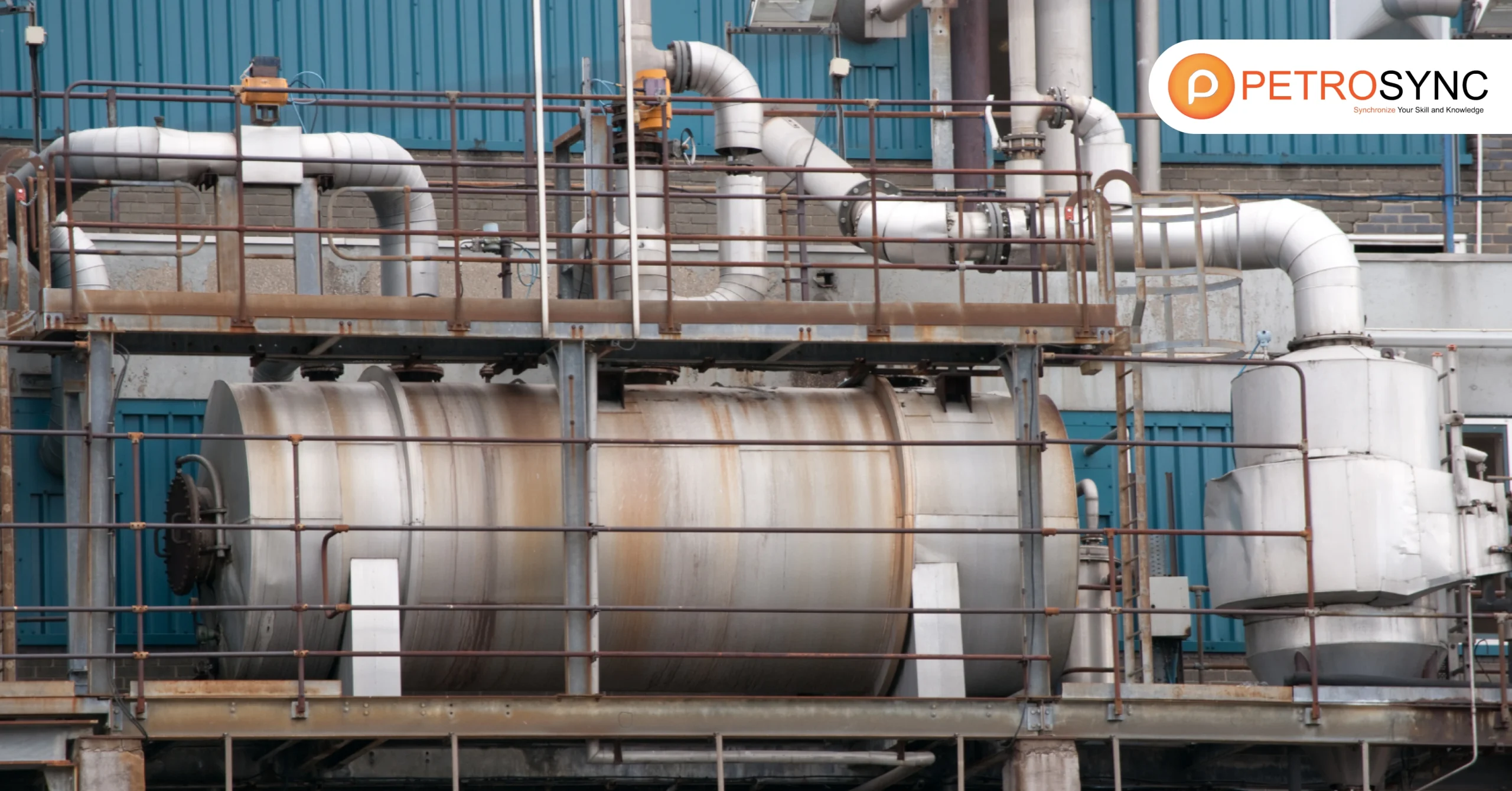
Shell and tube heat exchanger is a type of heat exchanging device constructed using a large cylindrical enclosure, or shell, that has bundles of tubing compacted in its interior. They designed this heat exchanger to transfer heat from one fluid to another fluid without them touching each other directly.
The design names this category of heat exchanger. Which includes a shell (as a sizable pressure vessel) housing a group of tubes. Watch the video below for the illustration. The tubes are enclosed by another fluid, such as water or air, and heat is transferred from the first fluid to the second fluid through the tube walls.
Tube and heat exchangers have various applications, such as in air conditioning systems, refrigeration systems, and industrial processes that require heat transfer.
When Shell and Tube Heat Exchanger Is Used?
People commonly use shell and tube heat exchangers when they require large-scale heat transmission. It is particularly beneficial when working with fluids at high pressures or temperatures. Industries in the petrochemical, chemical processing, and oil and gas sectors widely use shell and tube heat exchangers to ensure efficiency and safety.
Furthermore, engineers and industries widely use shell and tube heat exchangers when space is limited, and they require small yet efficient solutions. They also deploy these heat exchangers in situations involving corrosive fluids or significant temperature changes. The shell and tube heat exchanger’s flexibility makes it an appealing choice for cooling, heating, and condensing fluids in a variety of sectors.
These exchangers provide a stable and cost-effective option for refrigeration, power plant, and even food processing.
What Is The Industrial Use of Shell and Tube Heat Exchanger?
The industrial use of shell and tube heat exchangers, used in the chemical, food, oil and gas and other fields, is widespread. They are commonly employed in various industries for transferring heat between two fluids without direct contact. Some of the key industrial of shell and tube heat exchangers applications include:
- Heating and cooling processes in chemical plants
- Condensing and evaporating duties in refineries
- Heat recovery systems in power generation facilities
- HVAC systems in commercial and residential buildings
- Refrigeration systems in food processing plants
- Thermal management in oil and gas production facilities
Overall, shell and tube heat exchangers play a crucial role in optimizing thermal efficiency and maintaining temperature control across a wide range of industrial processes.
What Are The Components of Shell and Tube Heat Exchanger?
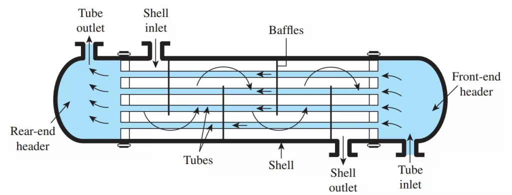
The components of a shell and tube heat exchanger can be broken down into the following parts:
1. Shell
The shell is the heat exchanger’s outermost part which holds the tube bundle. It is commonly a cylindrical container constructed from steel or other appropriate substances
2. Tubes or Tube Bundle
A collection of parallel tubes running along the length of the shell makes up the tube bundle. Depending on the specific use, the tubes can be composed of different materials, such as stainless steel, copper, or titanium. The diameter and thickness of the tubes are also important design parameters.
3. Tube Sheets
Tube sheets are sturdy sheets that act as a barrier between the tube bundle and the shell. They commonly construct them using steel and fuse them to the shell to ensure a firm and leak-free closure. They insert the tubes through holes in the tube sheets and either expand or weld them in position.
4. Baffles
Plates or rods called baffles regulate the movement of fluid around the tube bundle when placed inside the shell. They either align longitudinally or transversely and enhance the effectiveness of heat transfer.
5. Inlet and Outlet Nozzles
The inlet and outlet nozzles serve as the entry and exit points for fluids in the heat exchanger. Technicians usually place these connections at opposite ends of the shell and attach them to the tubes and the shell using flanges or other types of fittings.
6. Expansion Joints
Expansion joints are flexible connectors that accommodate the tube bundle’s thermal expansion and contraction. Usually located at the inlet and outlet of the heat exchanger, the engineers construct these joints using metal bellows or other flexible materials.
7. Support Structures
Support structures secure heat exchangers in place, providing a stable foundation. They can be temporary or permanent and made from steel or other materials.
What Are Some Types of Shell and Tube Heat Exchangers?
There are different types of shell and tube heat exchangers classified based on their design and intended use, as defined by the Tubular Exchangers Manufacturers Association (TEMA). These categories help in understanding the specific applications and requirements of each type:
1. Class B
These engineers design these heat exchangers for chemical processing applications. They construct them with materials and configurations suitable for handling corrosive substances and demanding chemical processes. Engineers build Class B heat exchangers to withstand the challenges posed by chemical environments.
2. Class C
This category encompasses heat exchangers intended for general commercial applications. These heat exchangers are versatile and can serve various industries with moderate operating conditions. They efficiently exchange heat in common commercial settings by design.
3. Class R
Engineers specifically tailor heat exchangers classified under Class R for petroleum and large-scale applications. They design them to handle the rigorous demands of processing petroleum products, including high temperatures, pressures, and flow rates. Class R heat exchangers are robust and suitable for industrial-scale operations.
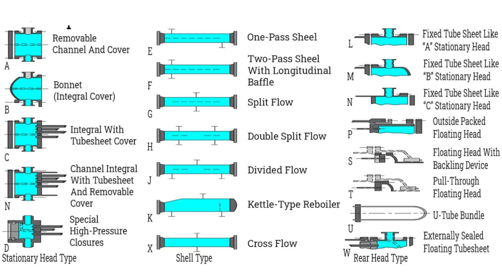
TEMA organizes shell and tube heat exchangers based on their components like the front end (head), rear end, and the shell. They use a chart with columns and rows to describe each type. To simplify identification, TEMA created a three-letter system (BEM, AEM, or NEN) for different designs of straight tube and fixed tube sheet heat exchangers.
The first letter in the code describes how the front end stationary head is connected to the shell and channel—either bolted (B) or welded (W). The second letter indicates the type of shell, including inlet/outlet positions, presence of baffles, and distribution plates. The third letter specifies the rear end head type and how the shell connects to the second tube sheet—bolted (B) or welded (W).
For example, a BEM heat exchanger has a bonnet header, a one-pass shell, and a fixed tube sheet, all identified using the TEMA system for clear categorization and understanding of different heat exchanger designs.
Understanding these classifications helps in selecting the appropriate shell and tube heat exchanger for specific industrial needs, ensuring optimal performance, reliability, and longevity in heat exchange processes.
How Many Types of Shell and Tube Heat Exchanger?
The three main types of shell and tube heat exchangers that people commonly use are essentially:
1. Fixed Tube Sheet Exchanger (L, M, and N Type Rear Headers)
In this design, the manufacturer welds the tube sheet to the shell, creating a simple and economical construction. While the team can clean the tube bores mechanically or chemically, they generally cannot access the outside surfaces of the tubes, except for chemical cleaning. Expansion bellows may be necessary to accommodate large temperature differences between the shell and tube materials, but they can be a source of weakness and failure.
2. U-Tube Exchangers
In a U-Tube exchanger, the front header types may vary, and the rear header is typically an M-Type. U-tubes allow for unlimited thermal expansion, and the tube bundle can be removed for cleaning. However, internal cleaning of the tubes by mechanical means is difficult, making this type suitable only for applications where the tube side fluids are clean.
3. Floating Head Exchanger (P, S, T, and W Type Rear Headers)
In this type of exchanger, the system allows the tubesheet at the rear header end to move or float instead of welding it to the shell. The system seals the tubesheet at the front header end, which has a larger diameter than the shell, similarly to the fixed tubesheet design..
We can accommodate thermal expansion, and we can remove the tube bundle for cleaning. The S-Type Rear Head is the most popular choice for the rear header. High temperatures and pressures suit floating head exchangers, but they are generally more expensive compared to fixed tubesheet exchangers.
How Does Shell and Tube Heat Exchanger Work?
Shell and tube heat exchanger works by transferring heat between two fluids, such as liquids or gasses. The fluids are separated by a solid barrier and flow through separate channels. One fluid travels through tubes while the other flows around the tubes in the shell.
As the fluids flow through their channels, the hotter fluid transfers heat to the cooler fluid through the barrier due to temperature differences and the barrier’s conductive properties.
The shell and tube design provides a large surface area for heat transfer, making it an efficient method to carry the heat between fluids. Furthermore, you can remove the tubes for cleaning or replacement without affecting the shell, which makes it easy to maintain and clean.
What Are The Advantages of A Shell and Tube Heat Exchanger?
The advantages of a shell and tube heat exchanger include its simple design, robust characteristics, and relatively low purchase and maintenance costs. This type of heat exchanger is widely used in various cooling applications due to these benefits.
The simple design of a shell-and-tube heat exchanger makes it versatile and suitable for a range of cooling needs. People commonly use it to cool hydraulic fluid and oil in engines, transmissions, and hydraulic power packs. Additionally, by choosing the right materials, you can also use these heat exchangers to cool or heat other mediums, such as swimming pool water or charge air.
Shell-and-tube heat exchangers are easy to service, especially models with floating tube bundles and non-welded tube plates.. This makes maintenance and cleaning more accessible, contributing to efficient operation and extended lifespan. The cylindrical housing design offers excellent pressure resistance, making shell-and-tube heat exchangers ideal for various industrial pressure applications.
Join PetroSync Training: Unlock Your Potential in the Industry
PetroSync’s Shell and Tube Heat Exchangers training course is a five-day course that aims to provide you with a thorough understanding of the ASME/ TEMA codes and standards related to mechanical design engineering, maintenance, repair, and testing of shell and tube heat exchangers.
We emphasize the importance of comprehending both the stated and implied requirements of the codes. You will also learn about the practical application of these code/standard rules and mechanical design formulas under different design conditions and services. Compared to other codes and standards like BS/DIN, ASME Section VIII/TEMA are easier to use and commonly adopted guidelines.
The course builds confidence in designing, maintaining, testing, and calculating strength of shell and tube heat exchangers.
The course will also provide case discussions to illustrate how to adopt code rules for different types of exchangers and service conditions. Let’s improve your heat exchanger performance by maximizing your mechanical design, operation, and maintenance knowledge with PetroSync!

Results-oriented and thorough SEO specialist with extensive experience in conducting keyword research, developing and implementing digital website promotion strategies and plans, managing campaigns to develop company websites in the digital world, excellent knowledge of marketing techniques and principles, and attentive strong attention to detail.

